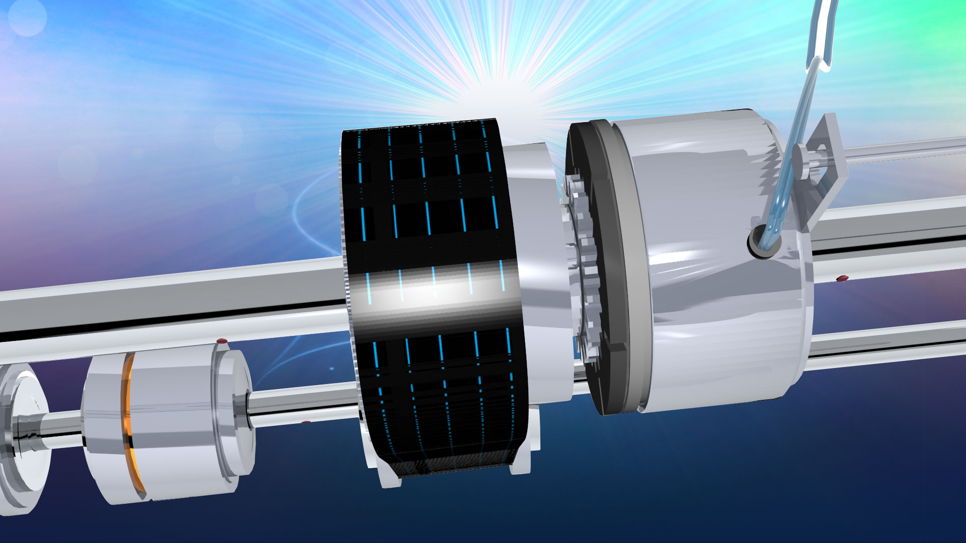

There are many types of electromagnetic clutches (tooth, multiple disc, hysteresis, magnetic particle). The most widely used version is the single face design. Electromagnetic clutches operate electrically but transmit torque mechanically. This is why they used to be referred to as Electro Mechanical clutches. Over the years EM became known as electromagnetic verses electro mechanical referring more about their actuation method verses physical operation. Since electromagnetic clutches started becoming popular, over seventy years ago, the variety of applications and clutch designs has increased dramatically but the basic operation of the single face electromagnetic clutch still remains the same.
Think of the coil shell as a horseshoe magnet having a north and south pole. If a piece of iron contacted both poles a magnetic circuit is created. In a clutch when power is applied a magnetic field is created. This field (flux) overcomes the air gap between the clutch rotor and the armature. This magnetic attraction pulls the armature in contact with the rotor face. The friction and the strength of the magnetic field, is what causes the rotational motion to start. Almost all of the torque comes from the magnetic attraction and coefficient of friction between the steel of the armature and the steel of the rotor or brake field. But for many industrial clutches, friction material is used between the poles. The material is mainly used to help decrease the wear rate. But different types of material can also be used to change the coefficient of friction for special applications. For example if the clutch was required to have an extended time to speed or slip time, a low coefficient material can be used. Conversely, if the clutch was required to have a slightly higher torque, a high coefficient friction material could be used.
In a clutch the electromagnetic lines of flux have to actually pass into the rotor and in turn, attract and pull the armature in contact with it to complete clutch engagement. Most industrial applications use what is called a single flux two pole clutch. Mobile clutches and other specialty electromagnetic clutches can use a double or a triple flux rotor. The double or triple flux refers to the number of north/south flux paths in the rotor and armature. These slots (banana slots) create an air gap which causes the flux path to take the path of least resistance. This means that if you have an armature that also has air gaps, what occurs is a leaping of the flux path which goes north-south, north-south. By having more points of contact you can greatly increase the amount of torque in a clutch. In theory if you could have two sets of poles at the same diameter you could double your operating torque from a clutch. Obviously that is not possible to do. So your points of contact have to be at a smaller diameter plus there are magnetic flux losses because of the bridges between the banana slots. But by using a multi pole design you achieve around a 40% increase with a double flux design, and a 70% increase with a triple flux design or from an application standpoint, design engineers can use a physically smaller clutch (saving weight and cost) verses a single flux design.
You can use a mobile clutch in an inside environment, but don’t use an Industrial clutch outside. Clutches used in most mobile applications do not use friction material. Many mobile clutches are exposed to the environment, so by not having material it avoids the swelling (reduced torque) that can happen when friction material gets wet .