Other Types of Electromagnetic Clutches

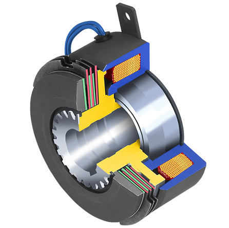
Introduction – Multiple Disc clutches are used to deliver extremely high torque in a relatively small space. These clutches can be used dry or wet (oil bath). Running the clutches in an oil bath also greatly increases the heat dissipation capability, which makes them ideally suited for multiple speed gear boxes, machine tool applications and automotive transmissions.
How it works – Multiple disk clutches operate via an electrical actuation but transmit torque mechanically. When voltage /current is applied to the clutch coil, the coil becomes an electromagnet and produces magnetic lines of flux. These lines of flux are transferred through the small air gap between the field and the rotor. The rotor portion of the clutch becomes magnetized and sets up a magnetic loop, which attracts both the armature and friction disks. The attraction of the armature compresses (squeezes) the friction disks, transferring the torque from the in inner driver to the out disks. The output disks are connected to a gear, coupling, or pulley via drive cup. The clutch slips until the input and output RPMs are matched. This happens relatively quickly typically (.2 -2 sec).
When the current/voltages are removed from the clutch, the armature is free to turn with the shaft. Springs hold the friction disk away from each other, so there is no contact when the clutch is not engaged, creating a minimal amount of drag.

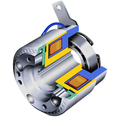
Introduction – Electromagnetic Tooth Clutches offer the greatest torque in the smallest package size. Because torque is transmitted without any slippage. Clutches are ideal for multi stage machines, where timing is critical such as, multi-station printing presses. Sometimes, exact timing needs to be kept, so tooth clutches can be made with a single position option, which means that they will only engage at a specific degree mark. They can be used in dry or wet (oil bath) applications, so they are very well suited for gear box type drives.
They should not be used in high speed applications or applications that have engagement speeds over 50 RPM otherwise, damage to the clutch teeth would occur, when trying to engage the clutch.
How it Works – Electromagnetic Tooth clutches operate via an electric actuation but transmit torque mechanically. When voltage/current is applied to the clutch coil, the coil becomes an electromagnet and produces magnetic lines of flux. This flux is then transferred through the small gap between the field and the rotor. The rotor portion of the clutch becomes magnetized and sets up a magnetic loop, which attracts the armature teeth to the rotor teeth. In most instances, the rotor is consistently rotating with the input (driver). As soon as the clutch armature and rotor are engaged, lock up is 100%.
When current/voltage is removed from the clutch field, the armatures free to turn with the shaft. Springs hold the armature away from the rotor surface when power is released, creating a small air gap and providing complete disengagement from input to output.

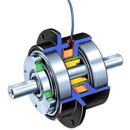
Introduction – Magnetic particle clutches are unique in their design, from other electromechanical clutches because of the wide operating torque range available. Like a standard, single face clutch, torque to voltage is almost linear. However, in a magnetic particle clutch, torque can be controlled very accurately. This makes these units ideally suited for tension control applications, such as wire winding, foil and film tension control and tape tension control. Because of their fast response, they can also be used in high cycle application, such as card readers, sorting machines, and labeling equipment.
Magnetic Particle Animation Video
A short animated movie overview that explains how a Magnetic Particle Clutch works
How it Works – Magnetic particles (very similar to iron filings) are located in the powder cavity. Without any voltage/current, they sit in the cavity. However, when voltage/current is applied to the coil, the magnetic flux that is created, tries to bind the particles together, almost like a magnetic particle slush. As the voltage/current is increased, the magnetic field builds, strengthening the binding of the particles. The clutch rotor passes through the bound particles, causing drag between the input and the output, during rotation. Depending upon the output torque requirement, the output and input may lock at 100% transfer.
When voltage/current is removed from the clutch, the input is free to turn with the shaft. Since the magnetic particle is in the cavity, all magnetic particle units have some type of minimum drag associated with them.

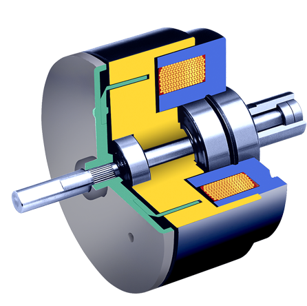
Introduction – These are a true electromagnetic clutch. Electrical hysteresis, although low in torque, units have an extremely wide controllable torque range. Since these units can be controlled precisely, they are ideal for testing application where variable controlled torque is required. Since drag torque is minimal, these units offer the widest available torque range of any electromagnetic product. Most applications involving powered hysteresis units are in test stand requirements. Since all torque is transmitted magnetically, there is no contact, so no wear occurs to any of the torque transfer components providing for extremely long life.
How it Works – Magnetic powder is positioned inside the housing of the OPL units. The exterior of the OPL unit is steel. The magnetic particles align along the lines of flux going from the permanent magnets to the steel housing which creaties a magnetic loop. The particles create friction as they drag against the steel housing. The strength of the magnet and the amount of particles inside the cavity determine the drag torque of each unit.
Larger OPL units use multiple magnets creating stronger bonds between the magnetic particle powder and the steel housing.
Larger permanent magnet hysteresis brakes use multiple curved segmented magnets in opposition to each other. These magnets act on a centered hysteresis disc which is attached to the unit’s shaft or hub. On the opposing side is an identical magnet that can be rotated as much as 45 degrees to create minimum to a maximum drag torque. In between the two magnetic discs is a hysteresis disc which is absorbed by the flux of the magnetic fields, but are held apart by a spacer.
An adjustment screw is used to hold the position of the magnets relative to each other. In a minimum torque condition the magnetic discs are aligned north to south. In this case, the flux travels straight through the hysteresis disc putting a minimum magnetic drag on the disc.
In a mid range torque condition, the discs are partially rotated, creating slightly more drag on the hysteresis disc. In the maximum torque condition, the discs are rotated until the fields are directly opposing each other, causing the magnetic fields to bump against each other, traveling circumferentially through the disc. The effect causes maximum magnetic drag on the disc.
